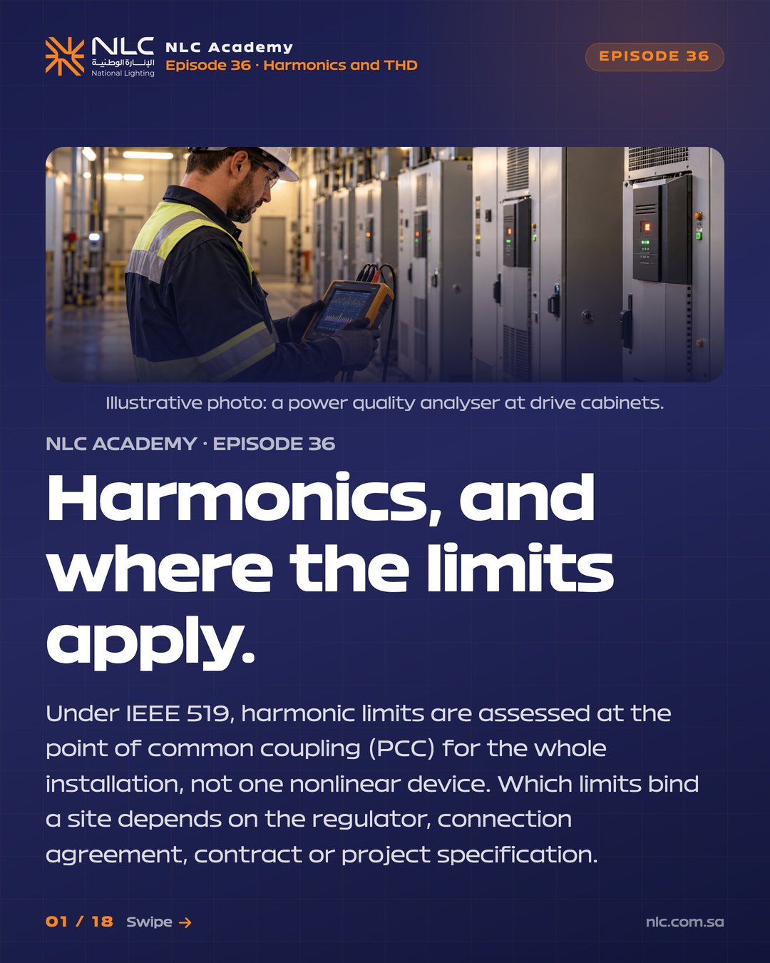
Non-linear loads draw current in pulses, not sinusoids, and the distortion reaches the whole supply. Under IEEE 519, harmonic limits are assessed at the point of common coupling (PCC) for the whole installation, not one nonlinear device. Which limits bind a site depends on the regulator, connection agreement, contract or project specification.
Four ideas to carry into the next specification conversation you have.
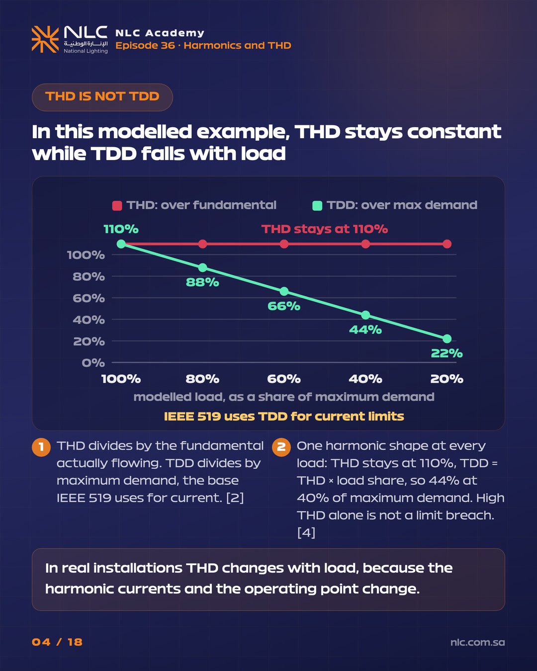
Both use the same numerator. THD divides by the fundamental actually flowing; TDD divides by maximum demand, the base IEEE 519 uses for current. In this modelled example one harmonic shape holds at every load, so THD stays at 110% while TDD = THD × load share: 44% at 40% of maximum demand. In real installations THD changes with load, because the harmonic currents and the operating point change. High THD alone is not a limit breach. The spectrum is an NLC illustrative model, not a measurement.
IEEE Std 519-2022 shares the duty at the point of common coupling: the system owner or operator for voltage distortion, the user for the harmonic current the whole installation injects. IEEE 519 limits are not meant for one piece of equipment. Equipment emission limits come from product standards such as IEC 61000-3-2 and IEC 61000-3-12, so judge the installation, not one nonlinear load.
IEEE Std 519-2022 (clause 3) defines it as a point on the public supply where other customers are, or could be, connected: for example the high-voltage side of a dedicated service transformer, or the low-voltage side of a shared one. A distribution board inside the building is not a PCC, so a THD reading there does not answer the PCC question that IEEE 519 frames.
A K-rating gives the transformer extra thermal headroom for harmonic heating. It does not reduce the harmonic current the installation injects into the network. Reducing that injection takes a different measure: a filter, an active front end or a multi-pulse rectifier. Name the fix for the problem you have: heating, or injection.
The SERA framework sets the Saudi voltage THD values in the table, and they are tighter than IEEE 519 at every level shown. IEEE Std 519-2022 Table 1 sets voltage limits by bus voltage at the PCC, and its limits are assessed there for the whole installation. Equipment emission limits come from product standards such as IEC 61000-3-2 and IEC 61000-3-12, so a site full of compliant products can still exceed the site limit. Use the values the connection agreement or specification adopts.
| Limit | Threshold | Where enforced |
|---|---|---|
| Voltage distortion, bus at or below 1 kV | 8.0% THD, 5.0% individual harmonic | IEEE Std 519-2022, Table 1 |
| Voltage distortion, bus above 1 kV up to 69 kV | 5.0% THD, 3.0% individual harmonic | IEEE Std 519-2022, Table 1 |
| Where the limits are assessed | the PCC, for the installation | IEEE Std 519-2022, clause 3 (PCC) |
| Is it binding? | not binding in all cases; binds once a regulator, utility, connection agreement or specification adopts it | IEEE Std 519-2022, clause 1 |
| Who carries the duty at the PCC | system owner or operator: voltage distortion; user: the harmonic current the installation injects | IEEE Std 519-2022 |
| Equipment emission limits | set by product standards, not by IEEE 519 | IEC 61000-3-2 and IEC 61000-3-12 |
| The metric for current | TDD, over maximum demand, not THD; limits set by the short-circuit ratio at the PCC | IEEE Std 519-2022, clause 3 (TDD) |
| Harmonic frequencies | 5th = 300 Hz, 7th = 420 Hz on the 60 Hz Saudi grid | SERA PQ framework (issue 1), sec. 6.6.1 to 6.6.2 (60 Hz); calculation |
| Voltage THD standard, 230 to 400 V | 5.0% | SERA PQ framework (issue 1), Annex 1 Table 5 |
| Voltage THD standard, 11 and 13.8 kV | 4.0% | SERA PQ framework (issue 1), Annex 1 Table 5 |
| Voltage THD standard, 33 to 69 kV | 3.0% | SERA PQ framework (issue 1), Annex 1 Table 5 |
| Where it applies and how it is measured | all connection points; IEC 61000-4-7, 10-minute intervals, at least one week | SERA PQ framework (issue 1), sec. 6.7.2 to 6.7.3 |
| IEC/TR 61000-3-6 and IEEE 519 | not referenced in the SERA framework | SERA PQ framework (issue 1) |

Five common assumptions, and what the standard and the physics say.
In a balanced three-phase, four-wire system, triplen harmonics (3rd, 9th, 15th) are in phase on all three phases, so they add in the neutral at three times the per-phase value. In the modelled switch-mode spectrum the 3rd is 81% of the fundamental, and in this balanced model the neutral carries 1.67 times the phase current. Load imbalance also produces neutral current. The modelled six-pulse drive has no triplens, so on a balanced supply it puts zero current in the neutral, at about a quarter of the switch-mode THD. The spectra are an NLC illustrative model, not measured, and a THD reading alone cannot size a neutral. Do not put neutral heating down to one cause without measurement or analysis.
On the 60 Hz grid the 5th harmonic is 300 Hz and the 7th is 420 Hz, not 250 and 350. Filter tuning written for 50 Hz, such as a filter tuned to the 5th at 250 Hz, does not carry over to 60 Hz without recalculation. An analyser set to the wrong fundamental labels every order wrongly.
In the modelled switch-mode spectrum the current is a narrow pulse, not a sine. Its peak is 1.81 times the RMS, against 1.41 for a sine. Equipment rated on peak current, such as a UPS inverter, may see that peak rather than the RMS. The 1.81 is a model result that assumes zero-phase harmonics, so a measured spectrum may differ.
IEEE Std 519-2022 (clause 1) states that its limit values should not be considered binding in all cases. The limits bind a site once a regulator, utility, connection agreement or project specification adopts them. The SERA Power Quality framework (issue 1) sets its own voltage THD values, applied at all connection points and measured to IEC 61000-4-7, and does not reference IEEE 519 or IEC/TR 61000-3-6. Use the values the connection agreement or specification adopts.
IEEE Std 519-2022 Table 1 sets voltage limits by bus voltage at the PCC: 8.0% THD and 5.0% for any single harmonic at or below 1 kV, and 5.0% THD and 3.0% single above 1 kV up to 69 kV. The SERA values in the table above are tighter at every level they cover. A hospital, data centre or airport that needs a tighter target writes it into the specification, with the value, the measurement point and the metric. Do not assume a stricter target from the site category.
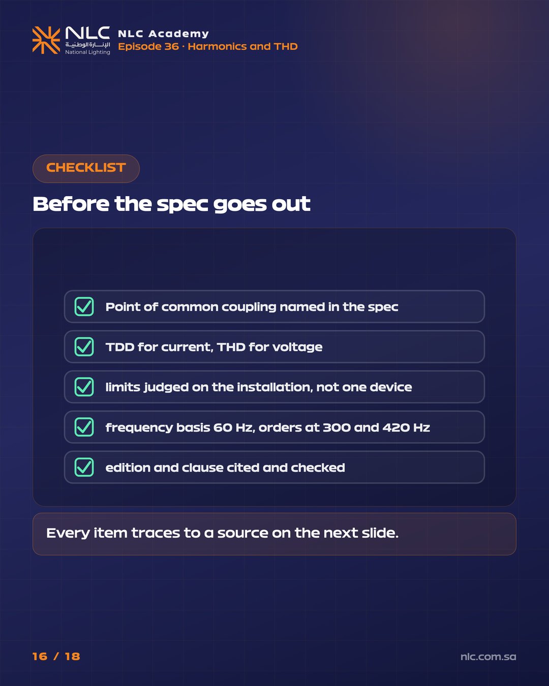
A THD reading at a sub-board does not answer the PCC question that IEEE 519 frames. Under IEEE 519-2022, current is compared with the TDD limits at the point of common coupling, and voltage with the THD and individual harmonic limits at the same point, on a 60 Hz fundamental.
Practical lighting know-how from NLC Academy. No spam, unsubscribe anytime.
By subscribing you agree to receive NLC emails.
Which document says it, and which clause.
A 18-slide explainer, ready to post straight to LinkedIn as an image carousel. Same content, faster reading.